Posted on

Marine, Caravan and RV Batteries

Which battery do I use, and why? Is there a difference between one brand of battery and another? How do I look after my batteries? We explain the difference and provide recommendations about which battery to use and how to look after them.

When you rely on batteries, as we do in our marine, caravan and RV lifestyles; it pays to have a better understanding of batteries, their construction, types, uses and how to look after them.

The fact that batteries usually only last about 2-3 years for most of us in these types of heavy applications is testament to how heavily we use, and how poorly we usually treat batteries. Batteries will actually last from 4 to 10 years when the correct selection is made for the use, then backed up by good charging practices and proper battery maintenance.

Firstly lets look at the criteria for rating batteries so that you might have a better understanding of how to compare batteries.

Battery Rating Criteria

Starting Efficiency – rates the ability of a battery to provide high amperage to “crank the engine” up to the starting RPM. This power comes off the surface of the plates; therefore, many thin plates will deliver the highest starting power.

Reserve Capacity @ 25 Amps @ 80°F – represents the time the battery will continue top operate essential accessories if the alternator or generator would fail. High reserve capacity ratings allow the use of more accessory power demands. This slower, lower discharge comes from the thicknesss of the plates. Thicker plates will deliver a higher reserve capacity.

Deep Cycle Capabilities – represents the ability of the battery to deliver small amounts of current over longer periods of time allowing the battery to withstand long, deep discharges, and long, slow recharges. Again, thicker plates perform better than thinner plates.

Dual Purpose Capabilities – represents the ability of a battery to provide ample starting power and moderate deep cycle service. This design is a compromise between a starting design and a true deep cycle design.

Non-Spillable Rating – is the degree of which the battery design ensures the prevention of leaks and spills allowing for added safety and numerous installation options.

Minimal Gassing-is attributed to the battery’s ability to control internal gas pressure, preventing capacity loss from extra gas seepage and allowing care-free use around sensitive electronic equipment. This assumes proper charging, because over-charging will drive hydrogen and oxygen from any battery design.

Recovery from Discharge Service (below 50%) – demonstrates the ability of the battery to be continually recharged from a discharged state below 50% of its full capacity without significant loss of capacity or life cycles.

Quickest Recharge Time @ 14.1 V or 14.5 V – shows the efficiency of a battery’s re-charge ability allowing for shorter charging times. Gel batteries are required to charge at a maximum of 14.1 V (14.6 V GelTech Battries) but only need to have 105% of the amp hours returned because they recharge so efficiently. In contrast, AGM battery’s are required to be charged at a maximum of 14.5 V, but will need 110% of the amp hours returned. A flooded battery can usually be charged at yet a higher voltage, depending upon the lead alloy; however, they will require 120-130% of the amp hours returned by the charging system.

Storage/Shelf Life-represents the rate at which a fully charged battery that is not being used can retain its charge. If the battery has a long storage life it will have a low self discharge rate and will be able to be inactive for a longer period of time (typical of off-season storage) without losing its capacity ratings or experiencing a significant decrease in its level of charge.

Deep Cycle Life (BCI 2 hr life) – shows the battery’s ability to be discharged to a low state of charge and then recharged for numerous cycles in controlled lab test conditions.

Less Sensitive Charging – shows the degree at which battery charging requires strict voltage control in order not to shorten or damage the battery’s life. For example GEL cell batteries must be limited to 14.1 V (14.6 V GelTech Battries) while AGM batteries can withstand up to 14.5 recharge voltage.

Low Initial Cost – compares the initial purchase price.

Long Term Value Cycling – determines the long term value of the battery by comparing the initial price in relation to the life cycles the battery design will deliver.

Durability – Overcharge Situation – evaluates the battery’s resistance to damage or capacity loss when it’s overcharged many times.

Durability – Ultra Deep Discharge – evaluates the battery’s resistance to damage or capacity loss by continually discharging close to its zero capacity rating.

Water Retention – shows the ability of the battery design and alloy composition to decrease the amount of water lost during the battery’s life. Some battery’s are designed to lose very little water during their life eliminating the need to add water.

Water Replacement – indicates if the vent caps or filter plugs can be removed to replace water that may be lost due to excessive gassing from over-charging situations.

Terminal Corrosion Resistance – is the battery’s design attributes that prevent acid residue that might cause unwanted corrosion on the terminals and attached wiring and/or nearby equipment. Terminal corrosion can also be relative to the battery’s non-spillable rating.

Flooded, AGM or GEL… which is best?

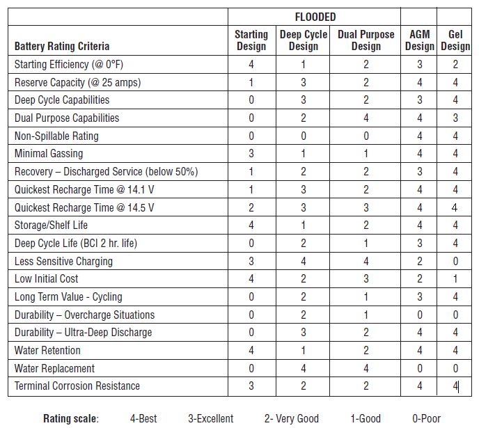
Below is a chart that rates flooded, AGM and GEL battery designs against numerous battery criteria that pertain to application use. See the explanations above  for terms to explain their relevance and importance in evaluating the different types of marine, caravan and RV batteries.
Construction

All batteries are not created equal. Automotive batteries generally do not suit marine use. We say generally, because some truck batteries are built tougher than the average automotive battery and may suit displacement vessels with large engine cranking requirements (starting amperage).

As you may appreciate, batteries in marine, caravan and RV situations are subject to more vibration, greater shock loads and high angles of inclination. Cycling batteries (deep cycle or house batteries) are also subject to much a deeper depth of discharge (DOD) than your average battery. Due to this heavy discharge, they  are then subject to heavy (and sometimes rapid) charging on a regular basis (sometimes daily) in order to replace the large amount of amps we have used up.

Your average battery just cant take this kind of treatment. Why?

  • Most automotive and/or poor quality batteries are not constructed strongly enough to withstand the loads applied to them in the marine, caravan and RV environment. If you think how comfortable it is for a car battery for a minute. They have a nice level place to sit, they just start the car (minimal discharge) and are then re-charged immediately, never being heavily discharged. They also reside in a constant temperature and have a low, steady maintenance charge rate from the vehicle’s alternator.
  • Excessive gassing when over-charged causes loss of electrolyte. This is a known problem in Valve Regulated Lead Acid (VRLA) batteries (also know as maintenance free batteries) as there is no way to top them up. High charging rates applied to a poor quality, maintenance free (or VRLA) battery will lead to low electrolyte, reducing the batteries life and eventually rendering the battery useless.
  • The sometimes violent motion with angles of incline up to 30° will cause the plates inside the battery to move, buckle, bend and eventually render the battery useless.
  • It is also worthy to note that USA made batteries conform to a standard, and so what they state on their spec sheet is usually true. Batteries made in other countries are not subject to such stringent regulation, and so you don’t always get what you pay for.

We have seen many Chinese batteries used in heavy discharge situations, such as electric trolling motors, anchor windlasses’ and bow thrusters in boats, or for house power use in marine, caravan or RV’s. Under these loads, and due to heavy discharge / re-charge, the battery gasses heavily, discharging its electrolyte, thus causing complete battery failure well within 12 months.

Batteries aren’t cheap at best, being let down by cheap batteries and installing them twice just doesn’t make economical sense, let alone the inconvenience and hassle.

Battery Type

There are 4 main battery types. Listed below are the type, application, advantage and disadvantage of each type.

TypeApplicationsAdvantagesDisadvantages
Gel Cell
Batteries
Marine, motorhome and RV house power.Cycling and heavy discharge applications.Electric vehiclesElectric trolling motorsHigh capacity (up to 225Ah – N200 case size)Wheelchairs and scootersGolf carts and trolleysPortable powerElectronicsTotally maintenance-freeAir transportableSpillproof/leakproofNo corrosionSuperior deep cycle lifeInstalls upright or on side (side installation may lose about 10% capacity)Very low to no gassing (unless overcharged)Compatible with sensitive electronic equipmentSuperior shelf lifeSuperior rechargeability (from 0% to 90% in 31⁄2 hours)No recharge current limitation @ 13.8 voltsRugged and vibration-resistantVery safe at sea with no chlorine gas in bilge (due to sulfuric acid and salt water mixing)Versatile: Starting, Deep Cycle, StationaryOperates in wet environments…even under 30 feet of waterWill not freeze to –20°F/–30°C (if fully charged)Lowest cost-per-month (cost ÷ months of life)Lowest cost-per-cycle (cost ÷ life cycles)Higher initial costHeavier weightWater cannot be replaced if continually overchargedAutomatic temperature-sensing, voltage-regulated chargers must be usedCharge voltage must be limited to extend life (13.8 to 14.6 volts maximum at 68°F)
Absorbed Glass Matt
Batteries
(AGM)
Marine, motorhome and RV house power (selected models)Engine starting (selected models)Dual application (selected models)Cycling and heavy discharge applications (selected models)Electric trolling motorsHigh capacity (up to 225Ah – N200 case size)Wheelchairs and scootersGolf carts and trolleysTotally maintenance-freeAir transportableSpillproof/leakproofNo corrosionInstalls upright or on sideLower cost than gel cell batteriesCompatible with sensitive electronic equipmentVery low to no gassing (unless overcharged)Excellent for starting and stationary applicationsSuperior for shorter duration/higher rate dischargesSuperior under extreme cold conditions when fully chargedSuperior shelf lifeSuperior rechargeability (from 0% to 90% in 31⁄2 hours)Rugged and vibration-resistantVery safe at sea with no chlorine gas in bilge (due to sulfuric acid and salt water mixing)Operates in wet environments…even under 30 feet of waterShorter cycle life than gel in very deep cycle applicationsAutomatic temperature-sensing, voltage-regulated chargers must be usedWater cannot be replaced if continually overchargedCharge voltage must be limited (14.4 to 14.6 volts maximum at 68°F) 
Flooded
Lead Acid
Batteries
(FLA)
Marine, motorhome and RV house power (selected models)Engine starting (selected models)Dual application (selected models)Cycling and heavy discharge applications (selected models)Electric trolling motorsHigh capacity (up to 225Ah – N200 case size)Wheelchairs and scootersGolf carts and trolleysLowest initial costHigher cranking ampsWater can be added (if accessible)Excellent for starting applicationsTolerant of improper recharge voltageCertain designs are good for deep cycle applicationsReplacements readily availableGood under extreme cold conditions when fully chargedSpillableOperates upright onlyShorter shelf lifeFewer shipping optionsCannot be installed near sensitive electronic equipmentWatering may be required (if accessible)
Lithium
Batteries
(Li-ion)
Marine, motorhome and RV house powerCycling and heavy discharge applicationsLight weight V’s Amps delivered (Energy density)Best system for cyclic applicationsLow self discharge rateBest depth of discharge (DOD)Highest number of cycles over life of batteryFast charge and discharge rateLow maintenanceHigh initial costRequires battery management system (BMS)Require specialised charging regimeImmature technology

SVR Gel Batteries

Sealed, Valve-Regulated (SVR) Gelled-electrolyte batteries offer many significant advantages over conventional “flooded” batteries. Gel batteries are spillproof* and leakproof, and resist over-discharges that can shorten the life of the battery.

Gel batteries have a self-discharge rate of less than 1% per month (at 68°F). They provide ample cranking amperage for quick, sure starts, and deliver longer trolling time than comparable flooded models. Their SVR design minimizes gassing, making them safe to install around people and sensitive electronic equipment. Gel batteries offer a viable alternative when you can only choose one battery.

Gel batteries are maintenance-free.

Charging: For longest life, always use a good, constant potential, voltage-regulated charger. For 12-volt Gel batteries, charge to at least 13.8 volts, but no more than 14.1 volts (14.6 V GelTech Battries) at 68°F (20°C). Do not charge in a sealed container.

SVR AGM Batteries

Sealed, Valve-Regulated (SVR) Absorbed Glass Mat (AGM) batteries use special absorbed electrolyte technology that is superior to flooded lead-acid batteries. Fine, highly porous microfiber glass separators absorb the electrolyte*, increasing efficiency by lowering internal resistance and boosting capacity.

Lower internal resistance also means that the batteries can be recharged faster than conventional batteries, allowing the user to put them back into operation sooner.

The completely sealed, valve-regulated AGM battery eliminates gas emissions and acid leakage for longer and safer battery operation. AGM batteries are also completely maintenance-free.

Charging: Use a good, constant potential, voltage-regulated charger. For 12-volt AGM batteries, charge to at least 14.4 volts, but no more than 14.6 volts at 68°F (20°C). Do not charge in a sealed container.

Flooded Batteries

Flooded lead-acid batteries are the most widely used batteries both in automotive and marine applications. Lead-acid batteries are usually less expensive than either the Gel or AGM batteries, but do not provide the same cycle life and convenience.

Most flooded batteries require maintenance. Electrolyte levels must be maintained above the cell’s plates.

Lithium Batteries

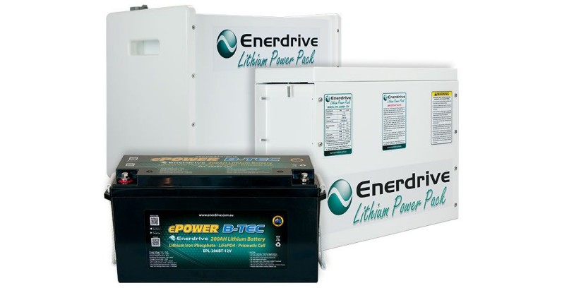
We only sell a complete Lithium battery system i.e. matched lithium battery and a battery management system. Enerdrive has a range of lithium battery kits to suit nearly every application, available in 100Ah, 200Ah, 300Ah, 400Ah & 500Ah capacities.

Lithium Ion batteries have a high energy density and are perfect for cyclic applications. They offer savings of up to 70% in volume and weight compared to traditional lead-acid batteries. Lithium batteries offer ult

Posted on

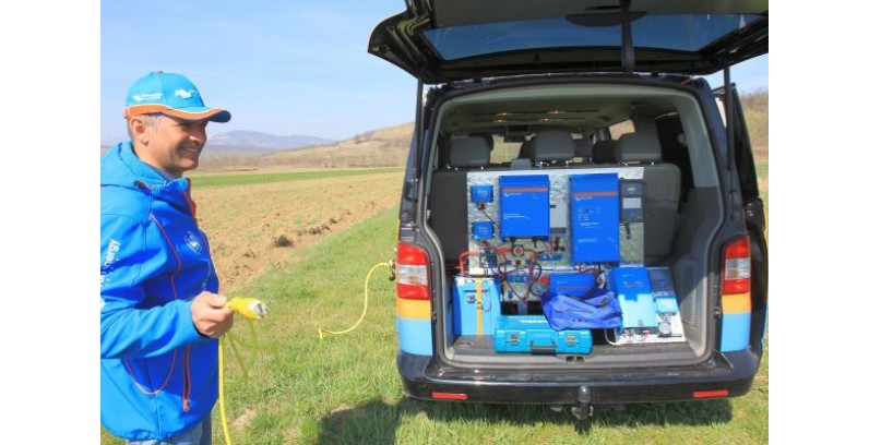
The Victron Van install

** Great Blog – Disregard the input/output 120VAC side of this set up we can design the system based on Victron’s 230VAC Inverter/Charger Combi to suit your needs **

Videos and schematics of the power systems installation

In case you missed these great videos and wiring schematics, we thought they deserved a blog post in their own right.

Victron Van – Video build episodes

  • Episode 1 – Solar: https://youtu.be/YW_xDerTycQ
  • Episode 2 – Alternator: https://youtu.be/vCOJ3nBFpIM
  • Episode 3 – Mains Electricity: https://youtu.be/TDSzfmHHjsA
  • Episode 4 – Color Control & Battery Monitor: https://youtu.be/2PyMIndbz6w

Outline Diagrams & Wiring Schematics for the Victron Van

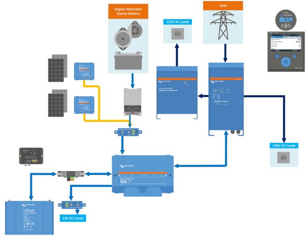
Outline Diagrams of the installOutline layout diagram – Click to enlarge image or see the Full Wiring Schematic PDF below.

  • Solar
  • Alternator
  • Full layout

Wiring Schematics of the install

  • Solar
  • Alternator
  • Grid
  • Full Wiring Schematic


Who needs a mains plug

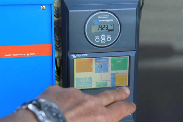
Total Control with Victron’s CCGX

Comments are welcomed on this install at the Victron Community website.

Conclusion

I think these videos by Jono (our video guy) do a great job of showing what can be achieved in a compact and mobile automotive application. Inspiration and system design for the VW Victron Van goes to Victron Energy Sales Manager, Lucian Popescu.

For more Victron videos check out the video section in the Victron YouTube Channel.

John Rushworth

Posted on

MasterVolt – Essential information when setting up an electrical system in either a New Vessel / RV or perhaps your completing a major refit

Information in this Blog was gathered from the Mastervolt website in order to offer a guide and explination into the world of Mastervolt and their MasterBus network system 

The MasterBus revolution

Mastervolt is your ideal system supplier. The products we supply fit seamlessly together and communicate easily to ensure a top system performance. Optimal operation is also provided by Mastervolt’s in-house developed communication and network platform: MasterBus.

The masterful MasterBus:

  • Complete system integration.
  • Simple to operate.
  • Easy installation.
  • Save on installation time and costs.
  • Easily expandable.
  • Perfect to monitor.
  • Ready for the future.

MasterBus is unique for the way a wide range of products, recognisable by the MasterBus symbol, are fitted with the same communication port. This results in a mine of information on all connected components. Everything becomes clear and easy to operate via one central touchscreen panel. Operation from multiple locations is also possible, for example via PC/laptop or SMS. Installation is also incredibly simple and the minimal amount of cabling significantly reduces the chance of failures.

Reliable

Thanks to galvanic isolation, nearly all Mastervolt devices can supply power to the MasterBus, ensuring a safe and stable network. Each MasterBus product has an ‘intelligence’ of its own and can function independently. This feature reduces the dependency of individual products and enhances the overall reliability of your system.

Flexible

New equipment can easily be added to your existing MasterBus network by simply extending the network. This means the MasterBus network has an enormous degree of flexibility, not just today but also in the future. Moreover, Mastervolt supplies various interfaces with which you can also connect equipment that does not have a MasterBus link. For example, we supply the MasterBus NMEA 2000 Interface for the integration of navigation equipment.

Mastershunt

Complete system

MasterBus is a network that makes use of CANbus technology, which already has a proven track record in the automotive and maritime markets. MasterBus controls the supply for all connected equipment, including the inverter, battery charger, generator and much more besides. This makes an intelligent system performance possible.

  • A practical example: The generator is instructed to start automatically when the batteries are almost empty.

Easy to install

MasterBus makes an electrical installation far less complex by reducing the number of cables. Each system component has two MasterBus communication ports. As soon as two or more devices are connected to each other via these communication ports they form a local data network – what we call a MasterBus network. As this requires very few communication cables you enjoy considerable savings in space, material costs and installation time.

Using your PC

The MasterBus USB Interface allows you to monitor, control and configure the entire MasterBus network from a Windows PC or laptop. The galvanic isolation of the interface ensures you safe operation in all situations.

Central operation

Mastervolt offers various control panels (touchscreen and otherwise) for the display and operation of the connected equipment, giving you a complete overview of the status of your electrical system. Control is at your fingertips and the full colour EasyView 5 panel allows you to read all information on one central panel. All control panels are suitable for the display, operation and configuration of all connected MasterBus devices.

Remote control

Communicating via your cell phone is no longer a pipe-dream. Using MasterBus you can request information and control onboard equipment via SMS. If desired you can even set the interface to inform your cell phone when an alarm goes off onboard.

How to create a MasterBus network

All devices that are suitable for the MasterBus network are equipped with two communication ports. As soon as two or more devices are connected with each other via these ports, they form a local data network. When creating a MasterBus network, follow the guidelines given here:

Masterbus regels

Connections between your devices can be made by using the Mastervolt UTP cables. The electricity needed for the network is supplied by the connected devices. At least one in every four devices in each network must be able to supply power to the MasterBus. For eight devices there must be two power suppliers, etc.

The remarkable simplicity of MasterBus events

Every MasterBus system can be set to your requirements – in essence, it’s like welcoming your own personal butler onboard. And MasterBus ‘events’ are how you train the butler. For example, you can set the generator to start automatically when the batteries are almost empty. Use MasterBus events to configure your system so that each component can activate another. MasterBus: At your service!

Example of an event

In the given example you set the following event: The batteries/battery monitor tell(s) the generator to start.

Say that you use the MasterShunt as a battery monitor within the MasterBus network. In this scenario the MasterShunt is the initiator or the ‘source’ and the generator is the ‘target’. The commando = start or autostart. The data = on. By setting multiple events (source, target, commando + data) you can program the entire MasterBus network.

Digital switching with MasterBus

Another example of a MasterBus event is the use of Digital Switching. The pressing of a light switch, for instance, activates the lighting. The source is the switch, the target the lamp. One source can also be used to control multiple targets, such as the lamps in this example.

Endless possibilities

Thanks to the underlying communication between all the equipment connected to the MasterBus network, the configuration of events offers you endless possibilities. If you wish, the switch in the example can, for instance, activate not only the lights but also the inverter that provides power to your TV.

All this and much more is available without the installation of extra components.

Summary

Within every MasterBus network all available sources for your connected products can be linked to all available targets. The manuals of the products concerned provide a clear overview of available sources and targets and simplify the configuration of events.

System Application Example:

Sailing profile

You normally go sailing for a weekend or midweek, sometimes anchored without access to shore power so you need enough power to cruise for two days. You also desire a range of comforts onboard, including a large refrigerator, microwave/oven combination and high-end coffee/espresso machine. Internet and email facilities are on your wish list as is (partial) navigation using your laptop, a good sound system and occasionally watching your favourite TV show.

Energy consumption

35-40 ft motoryacht

The basics

  • Your navigation station includes a GPS, plotter, speedometer and depth gauge. 
  • Your yacht has several pumps for water, shower, toilet and bilges. 
  • You require optimum ease of operation; not only centrally located but also next to your bed or in the engine room.

System choice

One of the advantages of using a Mass Combi is the ability to power loads even when mains supply is limited by using energy from your batteries. For example, a 10 A load can be powered from a 4 A shore connection. In addition, the design of the Mass Combi is both unique and characteristic of Mastervolt. Rather than installing heavy transformers, our lightweight, high-frequency technology offers major benefits regarding size, weight and sound (no hum!). The technology also ensures an exceptionally high efficiency with a minimal conversion loss and a low no-load consumption. The included battery temperature sensor will make sure the batteries receive the best possible charge. The Mass Combi meets all your requirements and more!

Batteries: 2 x MVG 12/140 Ah

The total of AC and DC consumers requires around 1 kWh per day (2 kWh in total). Totally discharging the batteries is not advisable so opt for a maximum of 50 % discharge = 4 kWh. Taking into account the various appliances and required peak loads we suggest a 12 V system. The required battery capacity is 4 kWh/12 V = ± 330 Ah.  

Charger/inverter: Mass Combi 12/1600-60

280 Ah needs at least 25 % of the battery capacity for charging power, so in this case we chose for a 60 A charging power via the Mass Combi. The Mass Combi has a battery charger that allows you to safely, quickly and completely charge two battery banks; starter and service batteries can be separately charged. Additionally the Mass Combi can be used to convert the power for your AC applications, so using everything simultaneously is also possible. 

Monitoring: EasyView 5

This touchscreen control panel is easy to read and operate. The grey button turns the display on or off or locks it, while all other functions can be controlled using the touchscreen. 

Digital distribution

The products in this system communicate with each other via MasterBus. This brilliantly simple platform for communication and connections ensures that all components ‘speak’ the same language. The result is a single communication protocol with high-speed CANbus technology.

1 x MasterShunt 500

MasterBus integrated battery monitor, with detailed information on the status of your batteries for an optimised charging process, incl. voltage, current, time remaining and consumption capacity in percentage. 

2 x DC Distribution 500 with 4 fuses

This distribution model connects up to four DC devices to the DC groups, such as a battery charger, inverter, alternators and solar panels. 

Other system components

  • 1 x AGM 12/130 starter battery. 
  • 1 x Mass GI 3.5 kVA/16 A; lightweight isolation transformer for safely using shore power, vital for steel or aluminium vessels to avoid electrolysis and corrosion. 
  • 1 x Charge Mate Pro; the ultimate solution for charging several batteries simultaneously, compatible with any type of alternator/charger. 
  • 4 x Shore Fix, 16A/30mA earth leakage switches. 
  • 1 x shore power cable 16 A, 25 m. 
  • 1 x shore power inlet 2+PE, 16A/230V. 
  • 2 x battery switches for switching on and off the consumers attached to the battery. 
  • 1 x Spotlight Chrome; the most versatile, durable, consistent and easy-to-use spotlight on the market.

Posted on

Lonestar Deep Drop Winch

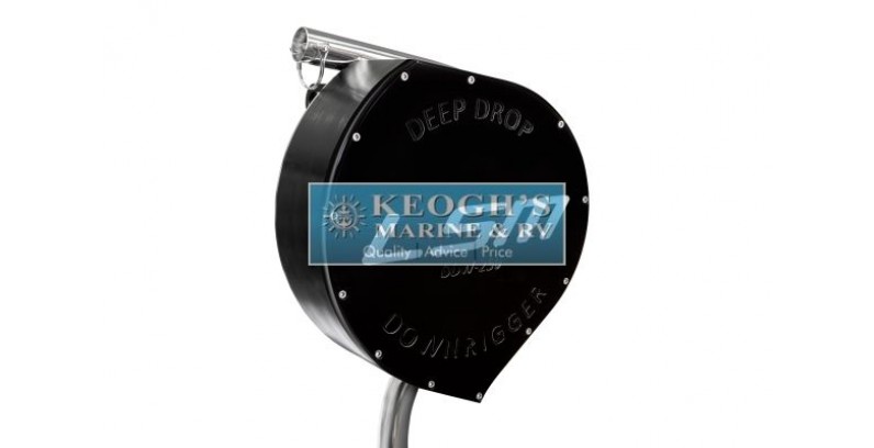
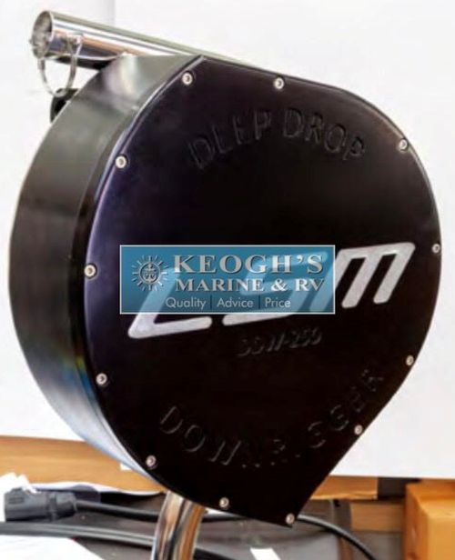
Introducing the Lonestar DDW-250 (Deep Drop Winch)
Contact us for Pricing & Pre Release Orders 

Our introduction to the features on the ** NEW DDW-250 **

1. Brushless Motors have replaced the previous brushed motors. There was nothing wrong with them but to be honest they were unnecessarily powerful all the time, and once we decided to add in our next feature it just made more sense to go brushless.

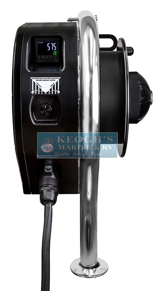
2. Variable speed. A true HD variable speed drive for an 800w brushed motor is quite expensive, they actually cost more than a brush less controller in that size, although the brush less motors cost considerably more. So when we decided to add variable speed it all made sense to change the motor. This will also reduce power consumption to use only what you need when you need it and reduces heat for those long duty cycles. This unit is only drawing 9 amps under light load and 20 amps under a standard load!

3. Single piece mainframe has replaced the 2 piece frame.

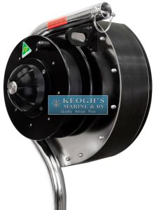
4. Larger, thinner spool with adjustable internal diameter-used in conjunction with the variable speed drive will give you an option for line retrieval up to 110m per minute when desired in 12v & 200m per minute in 24v! Yes the same unit can be used on either 12 or 24v! If also gives the owner the option to use either mono or braid, but with the braid spool insert you will not have to fill the spool with a great deal of mono backing in order to keep the spool diameter large.

5. New Drag-we have gone to a star drag as we had some customers finding the lever drag difficult to “tune” for their applications. The new star drag actually works better as all pressures are now isolated on the main shaft, where the previous at high drag pressure put a little load on the drive. Drag is now achieved through a 2 tier cork compression ring.

6. Digital Line Counter-Not a necessity in deep drop fishing, but they are handy to have and essential for those wanting to use this product as a down rigger. These are programmable to any value the operator likes, feet, meters, fathoms, ect.

7. Sleeker design. The drive side and all electronics are encapsulated under a single fascia, with all electronic panels and switches recessed along the outside.

8. 2 Boom options, e glass or stainless steel.

9. Australian Customers-The DDW still has a handle which can be added on in a few seconds to allow for legal fishing in all AU states except nanny state Victoria.  We are attempting to get a clear answer from Fisheries Victoria for the legality of this unit, as at the moment it is in a grey area. Still waiting on this…

10. The DDW-250 is for fishing/downrigging applications only. The GXC has been discontinued. We are are no longer making a “combo unit’ solution and have instead decided to make more made for purpose products in this area. This is the first of several new products scheduled along this line, expect to see a larger “Green Machine” long lining unit and all New Pot Hauler model available later this year.

Set to be a game changer for the Electric Reel Fishing Community 

** Upgraded Model is being released in June 2019 **

New Model features brush less drive, variable speed, line counter, 1 piece frame, wider drag curve plus more….more to be released shortly.

  • 316 Stainless Steel & Marine Grade 6061 T6 Marine Grade Anodised Aluminium Construction
  • Solid 38mm Drive shafts suitable for extended heavy loads
  • Brushless Variable Speed control *New for 2019
  • Italian Made Transmissions
  • Specialised for Deep Drop Fishing & Heavy Down-rigging
  • Line Counter *New for 2019
  • Changeable throat depth on spool for Mono or Braided lines *New for 2019
  • Up to 110m (375ft) per minute retrieval speed
  • Very high efficiency, as little as 10 amps under light load

Posted on

Victron Energy – Matching Solar Modules to MPPT Charge Controllers

Victron Blog – from Bob Hopman – Victron Energy

Matching solar modules to MPPT charge controllers

Life used to be so simple; in a 12V battery system you took a ‘12V’ solar module, watched carefully that the maximum PV current would not exceed the charge controller maximum current and the system would work.

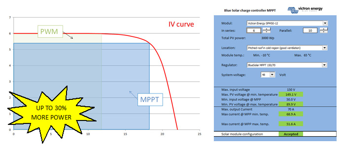
Unfortunately due to the fact, that with PWM controllers the PV module is not feeding the battery from its maximum power point (MPP), the system loses a lot of energy. In the following diagram you can see, the area of the MPP in blue  (Vmpp * Impp) is up to 30% larger than the PWM area (Vbatt * ~Isc) within the IV curve.

So, with the advent of the newer Victron Energy Blue Solar MPPTs, things changed for the better when compared to PWM solar charge controllers.

  • If a specific yield is the goal, the 30% higher efficiency of the MPPT will reduce system costs, because the same energy can now be produced with a smaller PV generator.
  • If the size of the solar module was already fixed, the yield is now higher in the same system when using an MPPT.

In both cases the user is a winner!

Sizing the system can be done electrically to see if the system is allowed and will not destroy any components, when looking at the yield to see how much energy it will produce. For now I will look at the first part, to find out what is possible on the electrical side.

By adding a DC/DC converter in the Blue Solar MPPT controller, the system also becomes more flexible when we look at the input voltage of the controller. The challenge now, is to match the PV modules to the controller, because we are not concentrating on only ‘12V’ or ‘24V’ modules anymore. Basically any module can now be used if it is within the input voltage range of the charge controller.

In fact we can now put modules in series as well as parallel, which will also increase the input power and flexibility. Thanks to the output power or current limiter, the output power will never exceed the maximum of the controller. This Blue Solar MPPT feature is unique and makes the charge controller even more interesting!

You can now for example add the same type of modules in parallel later without the need to change the MPPT charge controller. This reduces costs to a minimum, whilst still increasing the yield!

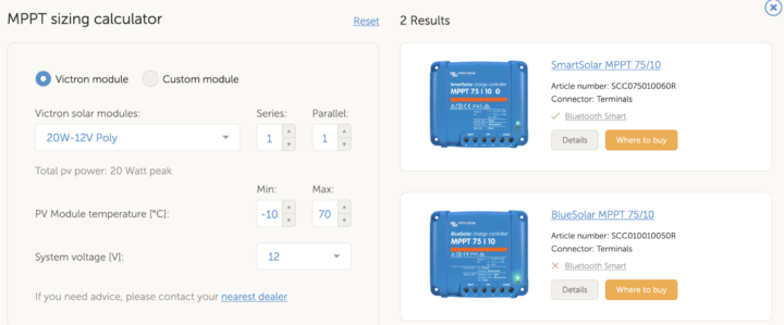
Also, I took the values for all our Blue Solar MPPT charge controllers and Blue Solar modules and combined them into a Spreadsheet. Now sizing a Blue Solar MPPT charge controller is easy!

Download: VE-MPPT-Calc.xlsx (744KB) – This configuration spreadsheet is compatible with MS Excel.

Now for the technical explanation, for those who would like to know some more details:

Exceeding the input voltage range will (as it did with the PWM controllers) damage the controller permanently.

Of course we will also need to take a look at the minimum voltage, where the Blue Solar MPPT controller will start working. If you take a SPM50-12, the Open Circuit Voltage (Voc) is 22.2V and the maximum power voltage (Vmpp) is 18V at Standard Test Conditions (STC) which means 1.000W/m² irradiation, 25°C cell temperature and an Airmass of 1.5. If the cell temperature is higher or less than 25°C, this voltage reduces or increases due to the temperature coefficient, in this case -0.34%/°C (see Blue Solar module datasheet).

So if you take 3 modules SPM50-12 on a Blue Solar MPPT 150/70 in a 48V system on cold days say, -10°C (only looking at the voltage), you can start up charging:

The startup voltage is 48V + 7V (see MPPT 150/70 datasheet) = 55V The modules will produce 3 * ( 22.2V + (-0.34% of 22.2V * -35°C temperature difference)) = 74.5V 74.5V is higher than 55V -> that’s perfect

Also running in the MPP the system would work:  

The running voltage is 48V + 2V (see MPPT 150/70 datasheet) = 50V The modules will produce 3 * ( 18V + (-0.34% of 22.2V * -35°C temperature difference)) = 61.9V 61.9V is higher than 50V -> that’s perfect

Doing the same thing, when the modules get warm during the day, in this case 70°C you can see what happens:

The startup voltage is still 48V + 7V (see MPPT 150/70 datasheet) = 55V The modules will produce 3 * ( 22.2V + (-0.34% of 22.2V * 45°C temperature difference)) = 56.4V 56.4V is higher than 55V -> that would work

But now in the MPP the module voltage is lower than the minimum:

The running voltage is 48V + 2V (see MPPT 150/70 datasheet) = 50V The modules will produce 3 * ( 18V + (-0.34% of 22.2V * 45°C temperature difference)) = 43.8V 43.8V is lower than 50V -> this is not enough!

The high DC/DC conversion efficiency (97.5% at 48V) will result in following output maximum charging current (@ -10°C) of 61.9V Vmpp* 2.74A Impp / 48V Battery voltage * 0.975 Efficiency = 3.45A This is far below the maximum of 70A, so it will be all used to charge the battery.

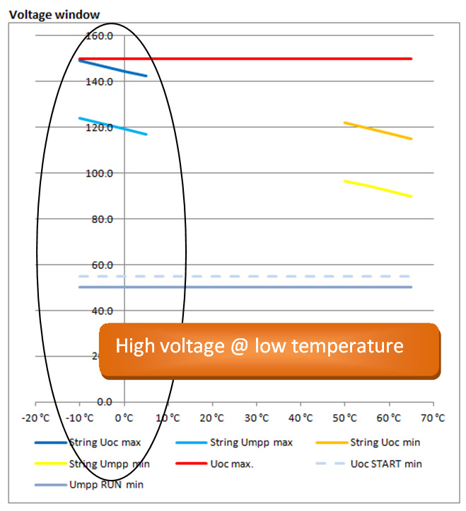
Increasing the number of modules per string to 6 in series and making 10 strings in parallel gives the following result at -10°C:

Voltage at low temp

The Voc will remain under the maximum of 150V at -10°C

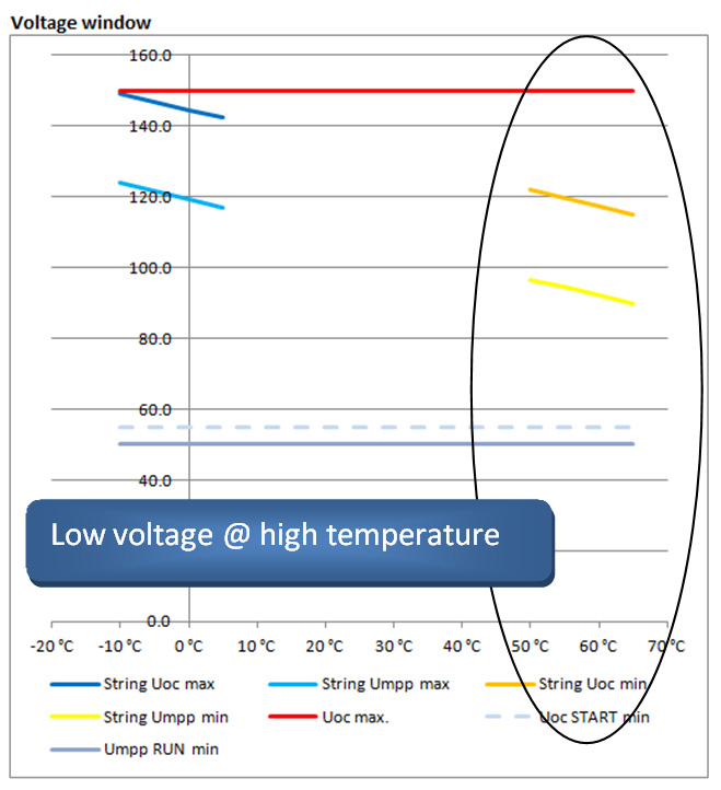
Voltage at high temp

Now at high temperatures such as a 70°C cell temperature the system will work just fine! Taking this example in the Spreadsheet you can now  increase the number of strings in parallel and you will see, if starting at 11 strings, that the controller will start to reduce power. The big advantage in doing this is that you will now produce the maximum controller output at a lower irradiation. As module prices decrease, this is an effective option.

Please note, that you can use ‘preconfigured’ minimum and maximum temperatures. I’ve also given some installation examples, at the bottom of the spreadsheet, with their anticipated module temperatures for various types of installations.

Oversizing a PV array

Oversizing a PV array is installing more peak power (Wp) than the maximum charge power of the chosen MPPT charge controller. A common reason to oversize is to cater for winter time.

How to determine by how much you can oversize a PV array? This can be done with help from the spreadsheet tool. Here though is the manual explanation of how it is done.

There are two limits, when determining the maximum array size that can be connected to an MPPT:

  1. The Maximum PV open circuit voltage (Voc at STC)
  2. The Maximum PV short circuit current (Isc at STC)

Both values are specified in the datasheets of all our MPPT Solar Charge Controllers. Those two ratings of the PV array must not exceed these MPPT limits.

Note that these two maximum ratings must not be multiplied to determine the maximum installable peak power. Instead, each of them needs to checked by itself:

Determining the maximum PV open circuit voltage

First look at the datasheets of the solar panels to see what their maximum open circuit voltage is. Then multiply that by the number of panels that are in series in the array. The result of the multiplication must not be higher than the Maximum PV open circuit voltage as listed on the MPPT Datasheet. Make sure to take into account the coldest expected temperature. The colder it is, the higher the open circuit voltage on a PV array will be.

Determining the maximum PV short circuit current

Get the maximum PV short circuit current from the PV Panel datasheet. Multiply by the number of panels in parallel in the array. Having more panels in series does not change the number.

The result of the calculation may not exceed the Max PV short circuit current as specified in the MPPT Datasheet.

Good luck and enjoy sizing the BlueSolar MPPT Charge Controller!

Kind regards,

Bob Hopman – Victron Energy